Project Background & Client Challenge
We recently visited a site in central London that had three cooling towers installed on the roof of their building in central London. The installation was approximately 20 years old and included a single side stream filter, which had recently been replaced, serving all three towers on site.
The client had stated that they believed that the side stream filter wasn’t working as well as the original installation and the main system circulating pump strainers in the basement required higher levels of cleaning than had previously been the case.
Looking at the installation, there were some clues as to why the system was not operating as effectively as it should have.
Identified Issues & Risks
1 – Return Connection Above Water Line
The return pipework from the sidestream filter entered the tower above the water line.
Returning water connection point.
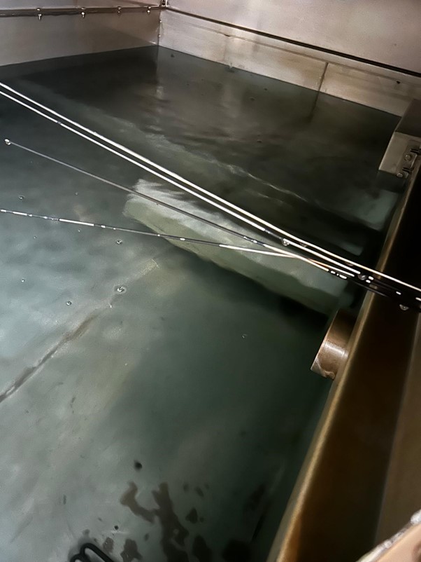
Having the returning flow entering the tower above the water line creates three potential risks:
- Causes splashing and potential drift (increased water loss).
- Aerates the water, which may increase fouling and corrosion risks.
- May create noise and require containment if the discharge is forceful.
By installing the return line below the water line, you can achieve the following advantages:
- Prevent splashing and aeration, which can decrease oxygen ingress, which promotes corrosion.
- Avoid drift losses and helps maintain water volume stability.
- Reduce noise compared to an above-water discharge.
- Maintain system pressure balance, especially in low-pressure side-stream systems (e.g. those running off a bypass loop).
2 – Offtake Position Under Main Discharge
The side stream filter return line was located directly underneath the main circulating line. This meant that any sediment moving towards the side stream filter offtake would likely have been drawn into the main circulating pipework.
Side stream off take directly below the main circulating pipework.
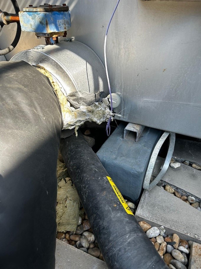
Best practice would be to locate the return line to the side stream filter on the opposite side of the sump to the main discharge connection so that sediment is drawn away from the main circulating process water.
3 – Sweeper System Installation
There was no sweeper system installed. A sweeper system is a system of directional eductor nozzles located in the sump of the tower, which direct the flow towards the side stream return.
Typical cooling tower sump sweeper system with eductor nozzles.
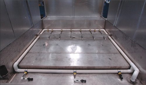
The sweeper system directs any sediment towards the sidestream return and away from the main circulating water flow.
These modifications will certainly help improve the filtration requirements for the cooling system.
System Optimisation & Hydrocyclone Sizing
It is also important to size the hydrocyclone for the capacity of the circulating water flow. Typically, in a commercial, non-industrial application, 10% of the system flow is suitable. For example, if the circulating flow is 300m3/hr then sizing a hydrocyclone to filter 30m3/hr is desirable. In more industrial applications, 15-20% would be advisable.
| Flow Rate (m3/hr) | Hydrocycone Filter Size (m3/hr) |
| 500 | 50 |
| 250 | 25 |
| 100 | 10 |
| 50 | 5 |
Additional Best Practice – Air Intake Filters
Where the debris and sediment in the system is being draw into the system through the cooling tower air intakes then installing air intake filter screens would be desirable. This simple upgrade:
Improves water quality, lowering corrosion and fouling risks
Protects the sump by trapping larger debris from ingress
Reduces solids load on side-stream filters and strainers
Extends equipment life and cuts cleaning frequency