Best Practice | Cooling System Pump and Pipework Design
This article raises the importance of getting cooling system pump design correct. The common symptoms of poor design are raised, and the best practice solutions are highlighted. Where problems are within existing systems, these issues can be designed out or remedied. Fortunately, these problems are usually few and far between, as typically, a high safety factor is employed when specifying pumps. But where issues are present, they can result in costly problems.
Incorrect Cooling System Pump Head Estimation
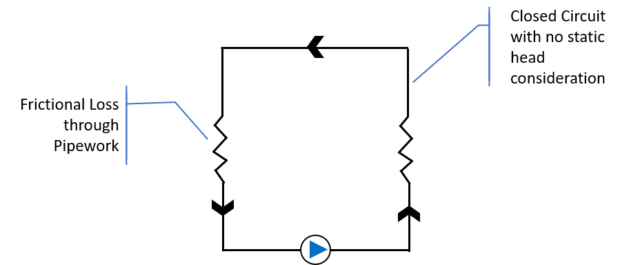
Closed Systems
In closed systems static head loss does not need to be considered. This is because there is a balance between the supply and return pipework. The static head lost to any height in the supply riser is cancelled out by a regain in the return pipework. Frictional loss is the only pump head requirement for consideration when sizing the pumps.
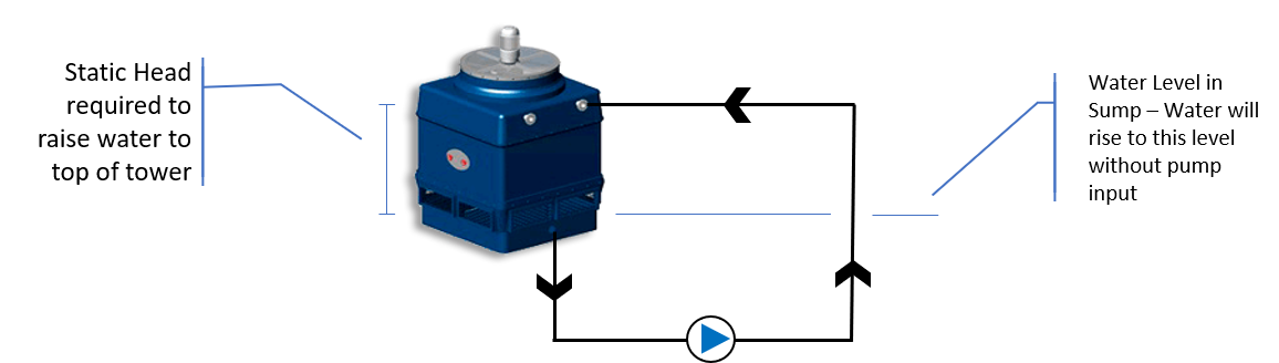
Open Systems
On open systems, like closed systems, the frictional loss through the pipework needs consideration. In addition, static headrequires careful consideration. In an open system, the static loss is not cancelled out. The pump is required to work to raise water from a low starting point to a higher point. The pump needs to be designed to overcome potential pressure drops through the system including:
- Pipework
- Cooling Tower
- Valves
- Condenser
- Static Head
- Distribution Nozzles
In certain designs of open tower systems, siphon draw can be established. This is where a siphon is created within the pipework above the distribution system level. This effect can be taken into account when establishing the total static head. However, by not considering this it allows the pump to be sized to accommodate a break in the siphon.
Cooling System Pump Curve Maintenance
- A tower bypass is installed in the suction line
- The cooling tower sump drains down on start up
- A Suction Vortex develops
It is possible to overcome the above problems by modifying the system design. For instance, if the tower bypass is installed within the suction line it can be modified and installed directly into the tower. This will eliminate air being drawn into the pump suction by removing the pressure differential between the flow and return lines.
Where the sump drains on start-up, this is typically the result of insufficient water to fill the system pipework and may result in air being drawn into the pump suction. These issues can be overcome with the installation of check valves and a fill line on the discharge side of the pump to fill the pipework. In addition, the installation of a anti-siphon loop at the high point in the system will minimise the amount of water flowing back into the tower creating overflow on shut down.
Tower suction vortices are caused when the water level in the sump is low relative to the flow rate through the suction line. This can also be caused by an undersized suction line which is smaller than the sump outlet size. As water exits the tower through a undersized pipe, its increased velocity causes a vortex.
These problems may be resolved by installing an anti-vortex fitting over the sump outlet and many cooling towers come with this as standard. Also, the pump selection head may have been over estimated producing high flows. Reducing the flow rate by throttling back the pump may resolve this issue bringing the pump back up the curve. In terms of pipework design, it is best practice to have more than 10 diameters of pipe at the same size as the tower suction connection before reducing its diameter.
Cavitation
Cavitation occurs within the pump when low pressure develops at the pump impeller that causes vaporisation or boiling. Typical problems associated with cavitation include:
Pump Impeller Damage – Low pressure in the impeller ‘eye’ causing vapour bubbles which implode as the bubbles move to higher areas of pressure within the impeller. These hammer like blows can cause damage as they hit the impeller repeatedly.
Inconsistent Pump Curve – The pump struggles with managing water then vapour and can result in flow virtually ceasing or becoming sporadic. This can result in the pump shaft being broken as it must handle the alternate streams of fluid, vapour and air.
Pump Seal Failure because of vapour flash around the seal causes a dry, ineffective seal.
To remove the risk of cavitation the Net Positive Suction Head (NPSH) must be considered. This ensures that pressure within the pump is above the vaporisation point for the fluid. Although fluid entering the pump suction may be at a sufficient pressure, it will always be lower within the pump interior at the impeller eye and vanes. The pressure drop across the interior of the pump must be understood. This will be defined by the pump manufacturer as the required NPSHr. It is not a constant and will increase as flow increases and similarly decrease as flow decreases.
Net Positive Suction Head available NPSHa, is defined as the total fluid head at the inlet of a pump. The formula to calculate NPSH is:
NPSH = PT-Pv
———————
PG
in which PT is inlet total pressure, Pv is vapor pressure of the fluid, r is density, and g is acceleration of gravity. The Net Positive Suction Head required, NPSHr, is a very important parameter for centrifugal pumps and will be given by the pump manufacturer.
When the NPSHa exceeds the NPSHr then the pump will operate satisfactorily. When the NPSHa is less than the NPSHr cavitation will result. It is therefore wise to allow a suitable margin between the two figures.
It is advisable to select a pump on the midpoint of the pump curve. Although the pump is larger, the impeller eye velocity will be reduced, and the internal pressure drop will be lower.
It allows for throttling back whereas a pump selected at the end of the curve will be more likely to have NPSH and cavitation problems.
Cooling System Pump Suction Line Issues
These are often caused by installation of valves and strainers in the pump suction line. If the pump suction pipe and pump are below the tower and the pump has been selected appropriately on the midpoint of its curve, then there will enough NPSH for the pump to work. High Pressure drops occur where valves and strainers are installed upstream of the pump suction. These should be installed in the pump discharge line as a standard. Where it is critical to install valves and strainers in the suction line then the effect should be carefully considered.
Strainers installed in the suction line may cause issues with pressure drop as they clog and result in cavitation. Pumps can pass relatively large objects. Strainers should be placed within the cooling tower sump which can easily be removed for cleaning. If protection of equipment such as a condenser or nozzles is critical upstream of the pump, then a finer strainer can be installed after the pump discharge. Sidestream filtration may be a solution that should be considered if suspended matter is an issue.
Conclusion
There are a number of issues that can affect the performance of a cooling system pump and each should be considered when designing a new or replacement system. It is important to understand the total head required taking into consideration both static and frictional head on open systems. There needs to be sufficient NPSH for the pump and this can largely be achieved through selecting a pump on the midpoint of the curve and locating the pump below the level of the cooling tower sump. The suction line from the tower should ideally be void of strainers where possible and if required, their impact should be calculated into the pressure drop when sizing the pump.
If any of these issues currently exist within your system or if you have any other questions surrounding pump performance that we can help with then please get in touch.
Lucy keeps the well oiled machine of Vistech Cooling running smoothly. She has close to a decade of experience working in the industry and creates industry-leading content that provides necessary information but also deeper insights into the field most people may not have considered.