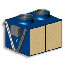
General Features
- Low sound level
- Low height
- No vibration transmission
- FRP Casing, reduced maintenance and total corrosion protection
- Plastic internals
Configuration
| Model | * Dissip. (kW) | Dry Weight (kg) | Service Weight (kg) | Recirculation Pump (kW) | Fan Power (kW) | Length (mm) | Width (mm) | Height (mm) | Dim. Drawing | Plane DWG | Technical Features |
|---|---|---|---|---|---|---|---|---|---|---|---|
| EWK-C 144/2 | 26 | 650 | 1190 | 0.75 | 2.2 | 2125 | 1269 | 2525 | Open | Download | [-] |
| EWK-C 144/3 | 52 | 750 | 1250 | 0.75 | 2.2 | 2125 | 1269 | 2525 | Open | Download | [-] |
| EWK-C 144/4 | 73 | 900 | 1440 | 0.75 | 2.2 | 2125 | 1269 | 2525 | Open | Download | [-] |
| EWK-C 225/3 | 99 | 1092 | 1789 | 0.75 | 3.0 | 2522 | 1557 | 2990 | Open | Download | [-] |
| EWK-C 225/4 | 128 | 1262 | 2024 | 0.75 | 3.0 | 2522 | 1557 | 2990 | Open | Download | [-] |
| EWK-C 225/5 | 165 | 1437 | 2264 | 0.75 | 3.0 | 2522 | 1557 | 3245 | Open | Download | [-] |
| EWK-C 324/3 | 180 | 1466 | 2368 | 1.5 | 4.0 | 2895 | 1850 | 3425 | Open | Download | [-] |
| EWK-C 324/4 | 203 | 1697 | 2695 | 1.5 | 4.0 | 2895 | 1850 | 3425 | Open | Download | [-] |
| EWK-C 324/5 | 230 | 1929 | 3024 | 1.5 | 4.0 | 2895 | 1850 | 3710 | Open | Download | [-] |
| EWK-C 441/3 | 218 | 1991 | 3280 | 2.2 | 7.5 | 3293 | 2150 | 3379 | Open | Download | [-] |
| EWK-C 441/4 | 301 | 2291 | 3776 | 2.2 | 7.5 | 3293 | 2150 | 3379 | Open | Download | [-] |
| EWK-C 441/5 | 383 | 2589 | 4202 | 2.2 | 7.5 | 3293 | 2150 | 3639 | Open | Download | [-] |
| EWK-C 441/6 | 401 | 2889 | 4638 | 2.2 | 7.5 | 3293 | 2150 | 3869 | Open | Download | [-] |
| EWK-C 680/3 | 383 | 3126 | 6070 | 4.0 | 7.5 | 3941 | 2319 | 4550 | Open | Download | [-] |
| EWK-C 680/4 | 410 | 3593 | 6743 | 4.0 | 7.5 | 3941 | 2319 | 4820 | Open | Download | [-] |
| EWK-C 680/5 | 450 | 4058 | 7415 | 4.0 | 7.5 | 3941 | 2319 | 4820 | Open | Download | [-] |
| EWK-C 680/6 | 490 | 4525 | 8090 | 4.0 | 7.5 | 3941 | 2319 | 5050 | Open | Download | [-] |
| EWK-C 900/3 | 492 | 3640 | 7145 | 4.0 | 11.0 | 4984 | 2020 | 4485 | Open | Download | [-] |
| EWK-C 900/4 | 555 | 4189 | 7946 | 4.0 | 11.0 | 4984 | 2020 | 4485 | Open | Download | [-] |
| EWK-C 900/5 | 559 | 4739 | 8750 | 4.0 | 11.0 | 4984 | 2020 | 4685 | Open | Download | [-] |
| EWK-C 900/6 | 639 | 5290 | 9554 | 4.0 | 11.0 | 4984 | 2020 | 4885 | Open | Download | [-] |
| EWK-C 1260/3 | 754 | 5757 | 11453 | 2 x 4.0 | 15.0 | 4285 | 3893 | 4770 | Open | Download | [-] |
| EWK-C 1260/4 | 921 | 6586 | 12677 | 2 x 4.0 | 15.0 | 4285 | 3893 | 4770 | Open | Download | [-] |
| EWK-C 1260/5 | 1109 | 7419 | 13909 | 2 x 4.0 | 15.0 | 4285 | 3893 | 4970 | Open | Download | [-] |
| EWK-C 1260/6 | 1250 | 8251 | 15138 | 2 x 4.0 | 15.0 | 4285 | 3893 | 5125 | Open | Download | [-] |
| EWK-C 1800/3 | 1046 | 7516 | 16408 | 2 x 4.0 | 22.0 | 5123 | 4300 | 4805 | Open | Download | [-] |
| EWK-C 1800/4 | 1319 | 8622 | 18022 | 2 x 4.0 | 22.0 | 5123 | 4300 | 5065 | Open | Download | [-] |
| EWK-C 1800/5 | 1486 | 9727 | 19631 | 2 x 4.0 | 22.0 | 5123 | 4300 | 5065 | Open | Download | [-] |
| EWK-C 1800/6 | 1610 | 10832 | 21242 | 2 x 4.0 | 22.0 | 5123 | 4300 | 5225 | Open | Download | [-] |
| * Heat rejection at the following conditions: Tin: 35,0 ºC, Tout: 30,0 ºC, Twb: 24,0 ºC | |||||||||||
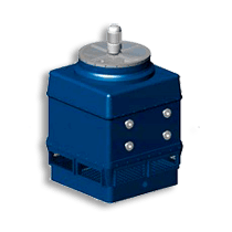
Additional Equipment
- Sound Attenuator.
- Access ladder & Hand rail to the fan motor.
- Vibration Switch.
- Electric water control level in the Basin .
- Winter Pack (Thermostat & immersion heater)
- Variable speed drives.
- Water treatment systems
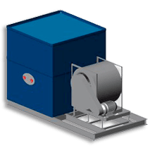
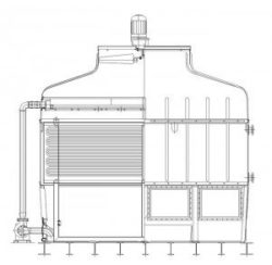
Working Principles
Evaporative cooling towers are the most energy efficient means of cooling water. Hot process water or condenser water from a chiller enters the distribution system at the top of the cooling tower and falls by gravity in counter-flow to the air being drawn or forced through the cooling tower by the fan. As the air passes the water a small proportion is evaporated cooling the remaining water which is collected in the cooling tower sump. The cooled water is then returned to the process or chiller.
The difference between the required cold water temperature and the wet bulb temperature (called the approach temperature), is significant in determining the size of the tower. The smaller the approach the larger the required heat exchange surface. The approach temperature must be at least 3-4 °C.
The heat exchange surface known as packing provides close contact between the air and water in open towers. High efficiency film packings provide a large surface area over which the cooling water is spread increasing the evaporative cooling effect. Splash packings can be selected for applications where the water quality is poor.